Elinchrom EL-Skyport Transmitter: Opening, design, schematics
I got a new light meter (the Sekonic L758DR) which unfortunately can not trigger my Elinchrom studio flashes remotely. Hence I want to built my own trigger module to fit into the L758 RF module slot. In addition I am always curious about the inner guts of my gadgets. Unfortunately the Internet could not help me a lot with information about the Elinchrom Skyport system. So I needed to start my own research. I will post some more information on this system whilst my design work goes on. Today I'm gonna discuss the design of the EL-Skyport transmitter (SPTX-V1.1) as well as some internal key components. This could come in handy in case you have to repair a broken unit, when a switch breaks for e.g.
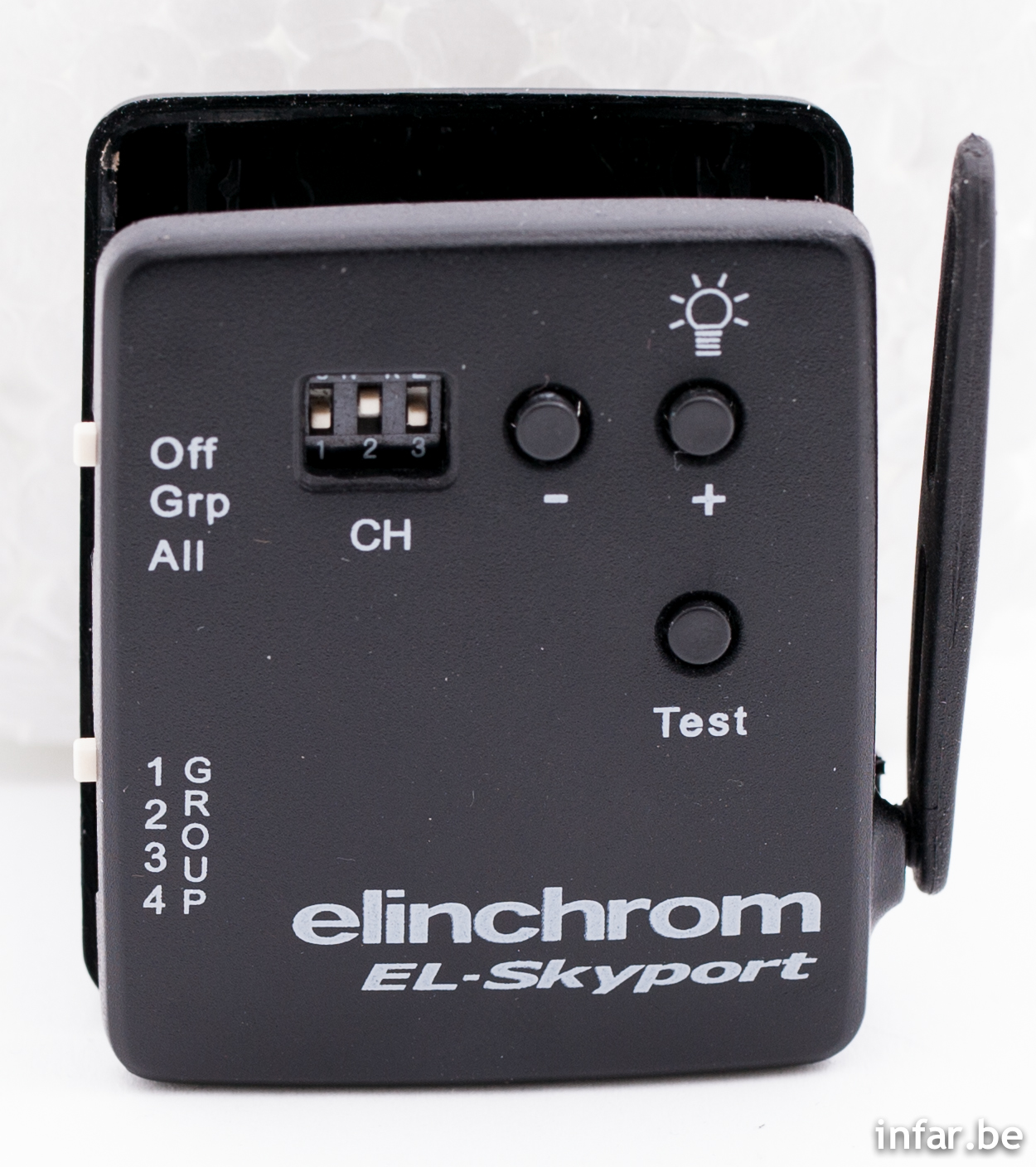
Elinchrom EL-Skyport Transmitter top

EL-Skyport Transmitter label
As you can see, my Skyport Transmitter SPTX has software version V1.1 flashed. Also clearly visible is the FCC ID. This always comes in handy to get first technical documents of electrical devices.
Opening the Case
First things first: How to open the case. Is it clicked together? Nope. It's glued, you have to crack it open carefully after removing the battery and its slider. (The glued case is also discussed in the documents Elinca S.A. handed in to get FCC approval of its Skyport system: "The plastic housing is glued and can not opened by the customer." You just have to search for the FCC ID UV7EL-SKYPORT on the FCC website to bring up the documents which are public. I like the "Operational Description" most.) What I used to help do the job is an old guitar pick, starting to pry where the two white slide switches leave an opening in the housing.
The below pictures show some details of the top cover. No plastic hooks, just glue.

Skyport Transmitter top cover.

Top cover detail.

Top cover detail - different angle.
Internal Pictures
After removing the four screws that hold the PCB to the top cover, we can further investigate the inner guts of the transmitter. Here are a couple of hi-res pics of the open case.

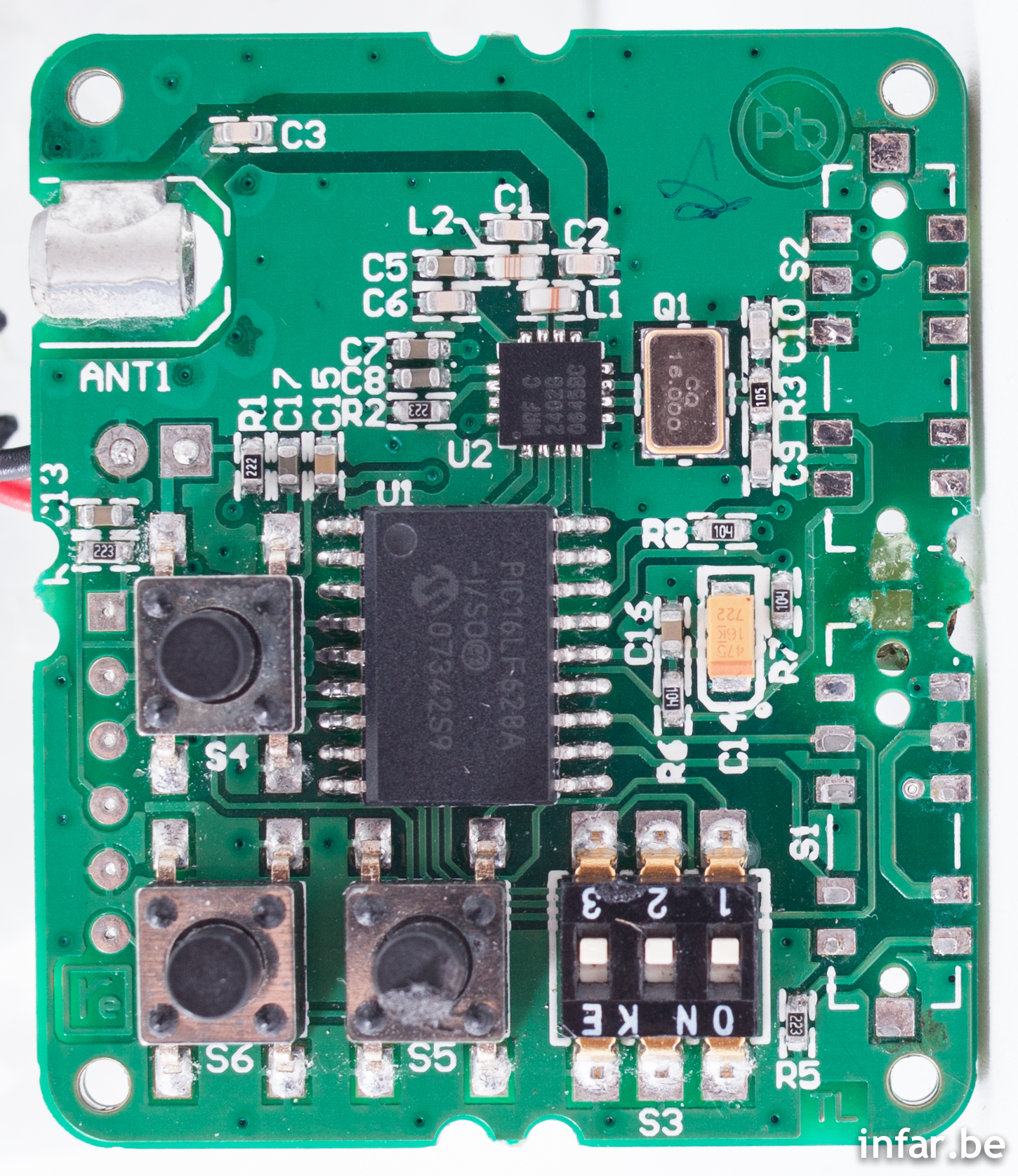
PCB in housing - top view.
You can easily recognize the parts that are visible from the outside: The antenna and switches. The key components of the Skyport Transmitter are a PIC microcontroller and a single chip 2.4 GHz transmitter IC with its 16 MHz crystal. There is not much more to discover.

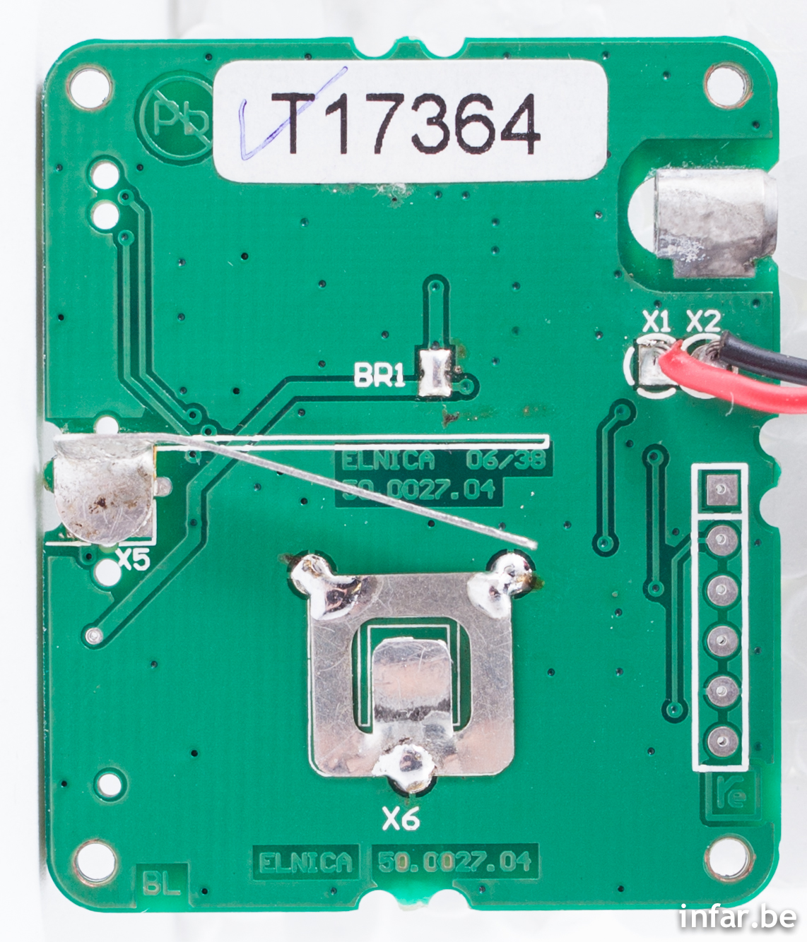
PCB bottom view.
The bottom side of the PCB hosts the contacts for the Lithium battery. Also, the flash sync signals(X1, X2) and battery (X5, X6) are connected here. On the right side you can see how the hot shoe and 2.5mm sync contacts are wired.
Microcontroller: Microchip PIC16LF628A
The heart of the transmitter is a Microchip PIC16LF628A Flash-based, 8-Bit CMOS microcontroller in an 18-pin SSOP housing, labeled as U1. It has a 4 MHz internal oscillator which is used in the Elinchrom application (there is no external crystal to the micro). The reason the design engineer at Elinchrom did choose the PIC16LF628A versus the non "L" version is that the PIC16LF628A works down to a supply voltage of 2.0 volts instead of the 3.0 volts of the PIC16F628A (keep in mind that the CR2430 battery is only 3.0V).
2.4 GHz Transmitter IC: Nordic Semiconductor nRF2402G
The RF part consists of the Nordic Semiconductor nRF2402G single chip 2.4 GHz RF transmitter IC which is labeled U2. Most of the surrounding components in the Elinchrom application are according to the reference application described in the nRF 2402G datasheet. The on air data rate the Skyport transmitter uses is 250 kbps. This is also mentioned in the "Operation Description" mentioned above.
Slide Switches: Copal Electronics CMS-2412A
The slide switches S1 and S2 to select the TX operation modes and groups are Copal Electronics CMS-2412A. I could not figure out the internal wiring of the switches as well as the supplier at the beginning. So I had to desolder them. This did also help me while drawing the schematics.
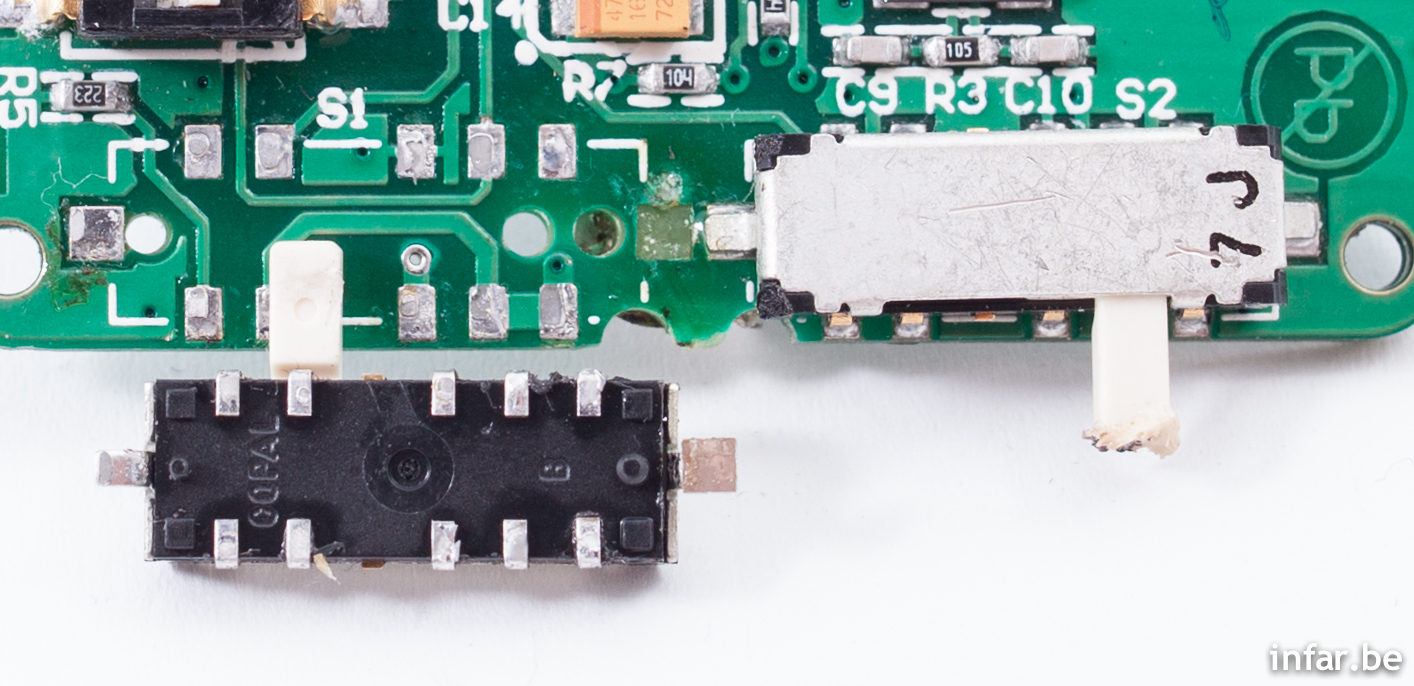
PCB top side detail with one COPAL switch desoldered (yes, I did burn the other one in a moment of nonattention).
SMD DIP Switch
The 3-way, 6-pin switch S3 used to select the Skyport operating channels is an ordinary SMD DIP switch. I did not do research to find out the exact part number or supplier name.
SMD Push Switches
The same applies for the standard SMD push switches which are used for the "+" (S6), "-" (S5) and "Test" (S4) buttons. I did not try to find out the exact part number as many different suppliers could be used in case a repair should be necessary.
Hot Shoe Connector
The hot shoe contacts are directly tied to the plastic housing of the Skyport Transmitter. In the schematics, it is denoted a J1.
2.5 mm Sync Connector
This is also no dedicated single part. J2 in the schematic.
Antenna Connector
The antenna connector is named as J3 in the schematics. The antenna can be removed from its jack when the case is opened but not when it is closed.
Programming Header
There are pads on the PCB which are used to program the PIC. In the schematics I named this header J4. I did not try to read out the PIC since I do not have the equipment at hand right now. I bet the FUSE bits are set anyhow. Anyone out there who might give it a try?
More Pictures
Finally there are two more hi-res pics of the Elinchrom EL-Skyport Transmitter internals. This time with the two slide switches removed to reveal the PCB wiring underneath.
Elinchrom EL-Skyport Transmitter PCB top view.
Elinchrom EL-Skyport Transmitter PCB bottom view.
Schematic
Finally I drew a schematic of what I saw on the PCB. For some components I could not figure out the exact value (especially L and C). I then added the value from the datasheet reference circuits when I was pretty sure the Elinchrom application uses the same. Where I think the application uses different values (especially in the antenna matching circuit), I put the datasheet values in brackets to give some orientation or no values at all.

More to come
There is a little more to come. I did decode all messages going from the PIC to the NRF2402G with a SPI protocol decoder. Together with the RF IC datasheet, I could figure out which settings are used for the configuration of the NRF2402G. I will write about this in an upcoming blog post. With this information, it is possible to build your own RF flash trigger for the Elinchrom Skyport system, maybe with an Arduino board as a starting point.

Following my dissection of the EL-Skyport Transmitter and drawing its schematic, I have further analyzed how this remote flash trigger works. Since a Nordic nRF2402G is used for the transmitter's RF part, the datasheet was a good starting point. The PIC
Tracked: Jul 11, 20:56