Elinchrom EL-Skyport Transmitter: Protocol and configuration
Following my dissection of the EL-Skyport Transmitter and drawing its schematic, I have further analyzed how this remote flash trigger works. Since a Nordic nRF2402G is used for the transmitter's RF part, the datasheet was a good starting point. The PIC uses a SPI bus to control the RF IC. So I mainly wanted to find out:
- How is the nRF2402 configured and when is the configuration done
- Which data is send to the nRF2402 via SPI while in operation
SPI Message Sniffing
According to its dataseheet, the nRF2402 is controlled via MOSI, CLK, CS and in addition CE and PWR_UP. What I did was simply probing these SPI lines between the Skyport's PIC controller and the nRF2402G to find out how the nRF2402G is configured for and which data is send to it while in operation.
![]()
SPI analyzer connected to the EL-Skyport Transmitter. Black and red is for power suply.
I also powered the EL-Skyport Transmitter with an external 3.0V power supply while testing.
To find out which settings the Elinchrom implementation is using, I did probe the configuration messages going to the nRF2402G. Configuration is only done right after power up and also after switching groups. Even if the Elinchrom manual says that you need to switch the transmitter off and then back on to activate a new channel setting, you could also switch groups.
The nRF2402G can only be configured when the CS line is pulled high, so I triggered for the CS line rising edge. For configuration, the CS line stays high for around 230 ms.

Configuration period is around 230 ms.
nRF2402G Configuration
The configuration is first done with an initial, "default" configuration message, which starts ~140 ms after power up and is always 3 67 CB. Around 85 ms after the first message, a second message with the actual channel setting is sent. This could then be 3 67 B8 for e.g.
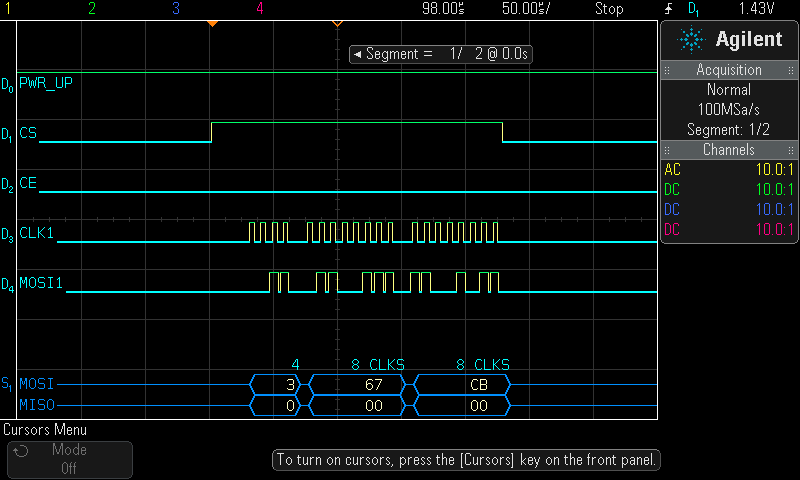
First part of the configuration message...

...and the second part of the configuration message.
When switching groups, the 2nd message is sent again, activating also a new channel setting (if you have switched the channels before). The default message is not sent before. SPI clock speed is around 100 kHz for configuration. But this is uncritical and can be selected according to the nRF2402G datasheet.
You could take a look at the nRF2402G datasheet to find out the configuration parameters. But I've made a nice colourful graphic to assist you.
![]()
EL-Skyport Transmitter default configuration
As can be easily spotted from the above picture, that the EL-Skyport Transmitter uses the nRF2402G with a standard transmissing frequency of 2475 MHz, a 16 MHz crystal, RF power is set to 0 dBm (chip maximum). The RF data rate is 250 kbps with burst mode and CRC generation enabled with 8 bit CRC and preamble generation (250 kbps and CRC gives you the best range and error robustness).
The only user selectable parameter affecting this configuration is the RF channel setting. So only the last byte in the configuration message changes with different channel settings. This can also be verified through probing all configuration messages on the SPI bus.

EL-Skyport channel settings and resulting configuration messages.
Trigger Messages
The following has been tested with a press on the "Test" button. Behaviour is the same as if the flash would be triggered via the hot shoe. For flash triggering, the contact needs to be pulled low. The trigger event for the PIC then is the falling edge, no matter how long the TEST line stays low. The transmission is initiated with the nRF2402G CE line. Thus this has been used for triggering.
First of all, the same message for flash triggering is repeated four times in a row. This adds redundancy to the signal and makes transmission more robust. But let's first take a look at the timings. After the hot shoe contact is pulled low, it takes about 65 µs until the PIC sets the CE line high and starts to clock out the trigger message.

Delay after trigger line has been pulled low.
In total, it takes the PIC roughly 180 µs until the CE line is set low again which initiates that the message is send out via RF on the selected channel.

Delay until the message can be send via RF.
The PIC finishes clocking out the last message around 2 ms after the trigger line has been pulled low.

Duration of one trigger event.
So in total, the worst case trigger delay now in terms of PIC to nRF2402G communication under the assumption that the first three bursts get lost in a collision or due to bad reception is about 2 ms. This is 1/500 th of a second. But then the nRF2402G still needs to send the last message via RF, the receiver needs to receive it and the processor in the receiver needs to recognize the message and trigger the flash. So the fastest sync time is probably between 1/500 th and 1/250 th of a second. Maybe I'll measure the whole chain when I've the chance to. Also, I assume that the Speed versions of the Skyport are faster here. Does anyone have one at hand to do the same measurements?
Now let's have a look at the messages itself. One single message contains 40 bit or 5 byte of data. The SPI clock rate is between 300 and 500 kHz, but again, this is uncritical. One burst is 100 µs long. There is a pause of around 500 µs between each of the four messages.
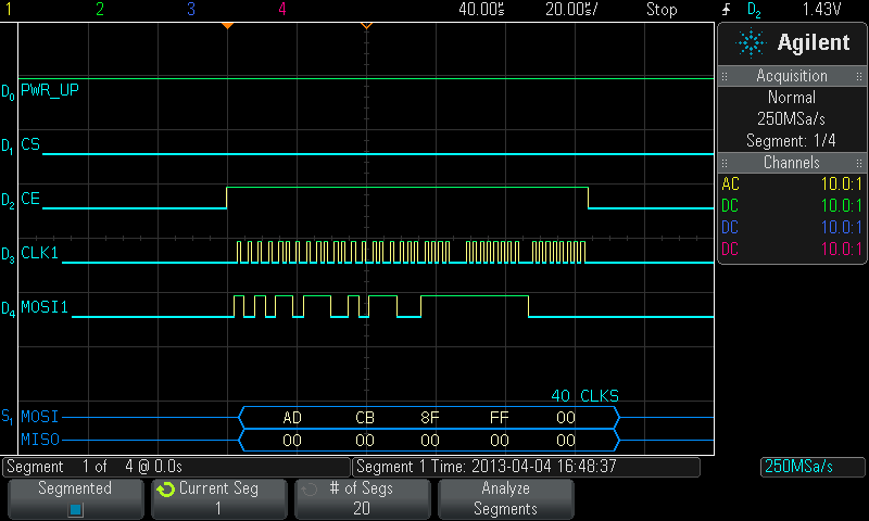
Trigger message for Mode switch set to All.

All Test/Trigger Messages
As can be spotted from the above table, the Group setting is coded in the 2nd last byte - this is the only part changeing when switching groups. So how is the trigger mode (Trigger, Plus, Minus, Modeling Light) coded? It will be proved in the next measurement, but I can already tell you that it is the last byte.
Plus and Minus Messages
The Plus and Minus buttons increase or decrease the flash power remotely. Unless with the Test button, the trigger event for the PIC when pressing Plus or Minus is not the falling, but the rising edge when the button is released again. Plus and Minus messages are similar to the trigger messages. But there is a difference in SPI clock timing (as stated before, this has no effect on the nRF2402G operation). This just causes a slightly longer delay until the message is sent via RF after CE is set low again. Also, the same message is only repeated once (two in total). For setting flash power, redundancy or robustness was not the primary design goal here. Also, timing is not so critical. The first message is initiated arond 7 to 8 ms after the button release.

Minus message after button is released.
The above plot also shows bouncing of the minus button when released. The last byte of the message is always clocked tinto the nRF2402G with a slower clock. Still no effect whatsoever. It's probably due to the software design of the application inside the PIC.

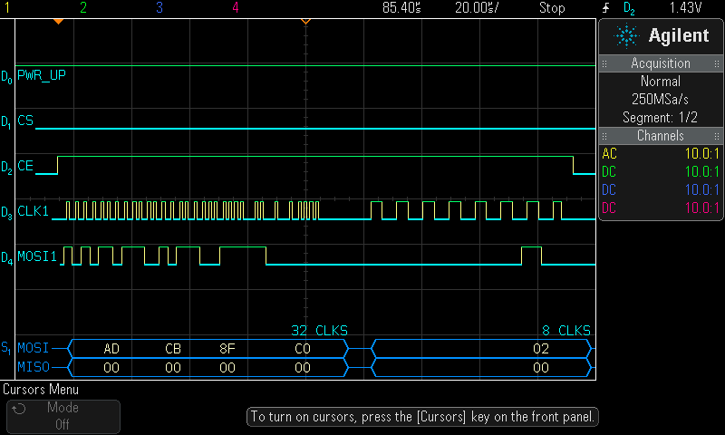
Plus message with Mode set to Group 1.
Minus message with Mode set to Group 1.

All Plus (+) messages

All Minus (-) messages
Now it gets clear that the last byte codes the mode (Trigger (0x00), Plus (0x01), Minus (0x02) and perhaps also Modeling Light).
Modeling Light Messages
As with the Plus or Minus Message, the Modeling Light message is sent
twice. The 2nd message begins after ~650 µs. Duration of the whole message (the
time CE stays high) is about 170 µs

First long press for Modeling Light.

Second long press for Modeling Light.
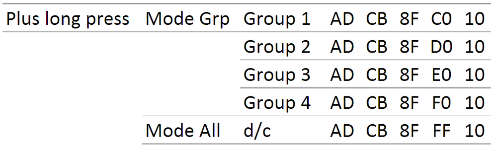
All Modeling Light messages.
So we see that also the Modeling Light is coded in the last byte. But there is a very important detail! The above table only shows 0x10 as the last byte. In reality, the last byte is alternated with 0x10 for the first long press, then 0x20 for the second one and then 0x10 again and so on. There is a good reason for this behaviour. If the receiver would receive two messages (two are sent out) it possibly could not distinguish if this is just a single message or parts of two messages. The question would then be to set the flash power one or two steps up? By alternating the messages, this problem can be overcome. And some more side information: It does not matter which
Group is selected, the first press of the button after power up always sets the
last byte to 0x10 and the second press 0x20 and so on. Switching
groups does not change the alternation scheme. If 0x10 is sent and then
the group is changed, the next long press will set the last byte to 0x20. But switching modes does change alternation and resets the last byte to be 0x10
for the first message to follow.
Address and Payload
To address the on air messages the nRF2402G sends out, a receiving address needs to be specified. According to the nRF2402G, this can be 8 to 40 bit long. So, let's take a look at the above messages, they all look like this: AD CB 8F FF 00. We already know that the last byte codes the function and the second last byte the group. So my first assumption would be that AD CB 8F is the receiver's address. But there is a probability that maybe only the first or the first two byte could be the address and that the other byte(s) code something else. So that's something which still needs to be proved. Ideally through hooking up the same probing setup to the Skyport Receiver's internal SPI port or through simly configuring one, two or three byte long addresses with an own setup (see last section).
Bugs
I discovered a quirk during my analysis. Maybe it is intentional design, but I'll call it a bug.
The first time the Test button is pressed (or flash is triggered via the hot shoe) after a new Group has been selected, the PIC sends the message for the old group. From the
2nd press onwards, the right message is sent. If the mode is changed from
Grp to All or vice versa, the right message is transmitted already at
the first press of the Test button. This explains that my Ranger "does not work correctly" after I changed Groups. The 2nd shot then always was okay.
Summary and Outlook
I think this is just the beginning of understanding the Elinchrom trigger protocol. There is so much more to discover. I'd like to get my hands on a Speed set to see which messages are send out there. Also the USB dongle would be nice to test. So for my next step I already bought some cheap nRF24L01+ modules and hooked them up to my Arduino. I choose the nRF24L01+ over the nRF2402G since it is the recommended successor. It does not only have a transmitter, but also a receiver built in. My hardware setup looks similar to the one maniacbug has published here. Also, you can find some very good explanations and code for getting started with the nRF24L01+ on Arduino on the site. I'll see if I will use this library or if I will just code what I need to operate the Elinchrom system. The nRF24L01+ needs some porting work as you cannot use the same SPI messages and SPI bus handling as with the nRF2402G. If you can get your hands on some leftover stock of this older IC at alibaba.com, then you could use the exact SPI messages descibed above.
This all is part of my 2013 pet project to design a RF module for my Sekonic L758DR which can trigger my Elinchrom system. Yes, there is a solution available, but it is not openly documented.
One nice small project which also could come out of this work above could be a small and handy flash power remote. You would just have Plus, Minus and a dedicated Modeling Light button on a small remote around your neck. Myself, I do not like to fidle around the tiny switches when I have my camera mounted on a higher tripod. Also switching the Modelling Light is a nightmare. Did you press long enough or too short and accidentially changed the flash power setting...
Finally: All comments, questions or corrections to the above are welcome. I also recommend again that you get familiar with my article about the inner guts and schematic of the Elinchrom EL-Skyport transmitter if you are not already familiar with it.
