Elinchrom EL-Skyport triggered by Arduino
After figuring out how the Elinchrom EL-Skyport Transmitter works, I wanted to do a proof of concept implementation with an Arduino. This would allow me verifying my assumptions I made in my previous investigation. The hardware is based on an Arduino Leonardo equipped with a cheap (< 4 USD) nRF24L01+ module. After powering up the Arduino, it sends out a trigger pulse to the EL-Skyport Receiver every 500 ms.
Here is how it works.
Hardware Setup
The original EL-Skyport transmitter uses a Nordic nRF2402G chip, as I have described here. You could hook up this chip to the Arduino, but I would not recommend in doing so. Neither does Nordic, because the chip has reached EOL. Instead, use a nRF24L01+. I bought a ready module for EUR 2.5 (~USD 3.4). They are easy to get via eBay. Make sure you use the plus (+) version. The modules look like this:
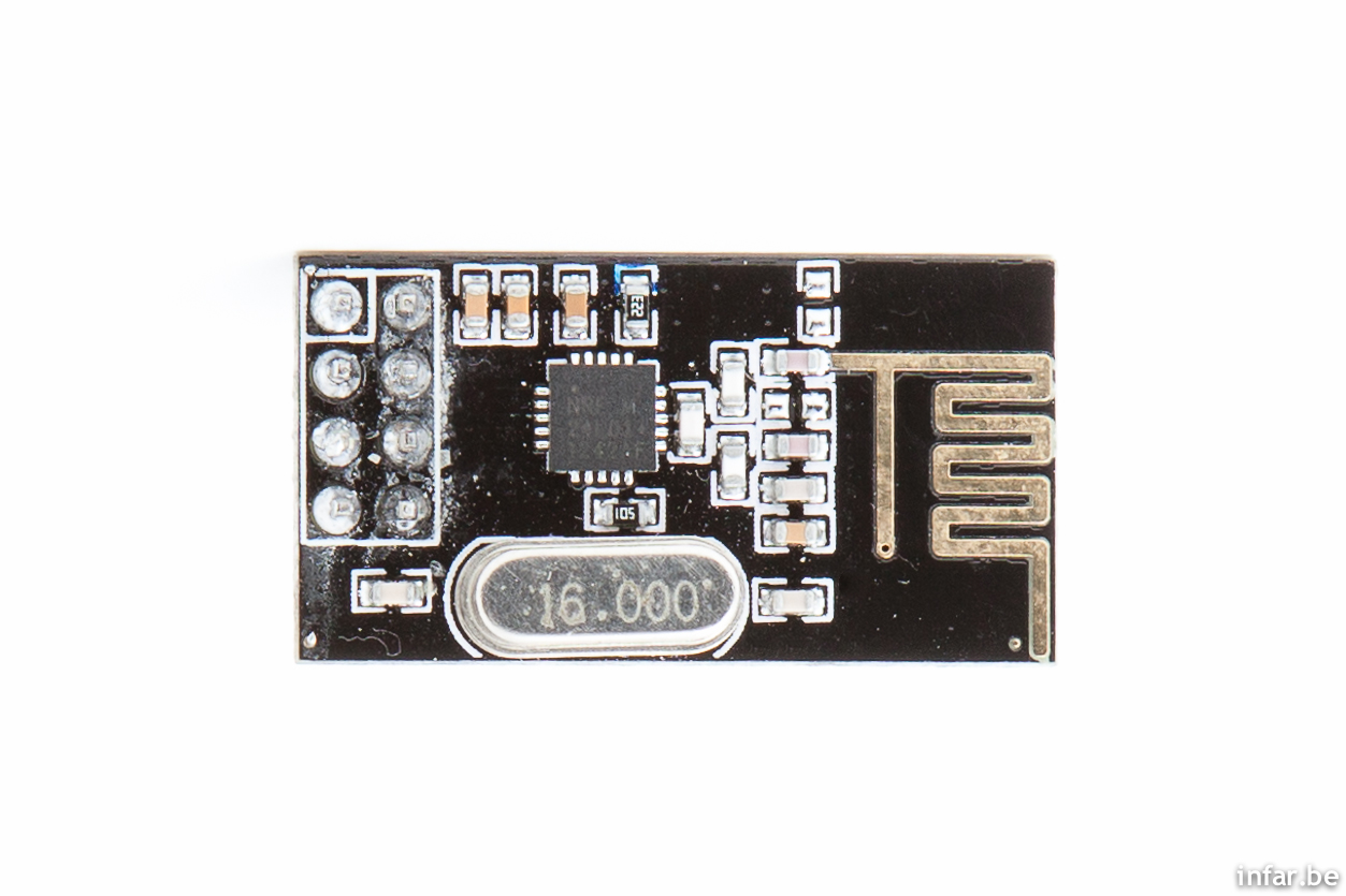
It comes with a standard 2.54 mm pitch connector (power, data via SPI bus) and the PCB already includes an antenna. I just made a quick adaptor board to place the module on top of the Arduino Leonardo. The pinout of the module I used can be found at various places, here is just one example. If you buy a different module, the pinout may be different as well.

The Leonardo does not have SPI on the two side pin headers anymore (as with previous/other Arduino boards). So I had to use the ICSP header for SPI. For older boards, you can just follow maniacbug's instructions for connecting the module to the Arduino.
I have also connected the module's IRQ pin to the Arduino pin 2. You don't need to do this if you just want to follow this proof of concept (it is used for more advanced controlling). The nRF24L01+ is 5V tolerant for all the data lines and can be connected to the Arduino directly without level shifters. But please make sure to only use the +3.3V pin for power supply (not +5V). The Arduino does supply enough current to operate the module.

I also made sure to expose the module a little to keep the antenna free from influences of the PCB, not to compromise on transmitting range.

And that's how the complete assembly looks like next to the EL-Skyport Receiver.
Source code
For controlling the nRF24L01+, there are already two good Arduino libraries available. One is the mirf library and one is maniacbug's excellent RF24 library. But I wanted to keep my source code to a minimum and allow for easy understanding and easy portability to other microcontrollers. So I just coded the bare minimum SPI commands. Based on this it should be fairly easy to do a full implementation of the EL-Skyport Transmitter if you follow my protocol description and the comments in the code.

I've done my implementation with the Arduino 1.0.1 IDE but it should work with newer versions as well. And here is the source code if you want to play around with it.
Outlook
Now what are the next possible steps for someone who can trigger the EL-Skyport system with an Arduino, Raspberry Pi or other microcontrollers? There are several possible projects which I am thinking of.
Increase the range of the EL-Skyport Transmitter
Not satisfied with the range of the original EL-Skyport transmitter? You could possibly violate some laws in your home country. But instead of the nRF24L01+ module described above, you could use the modules with built in transmit power amplifier. They are almost as cheap as the usual modules. But keep in mind that you must power them with an external 3.3V power source. The +3.3V Arduino power source is not strong enough.They also come with a nice antenna socket, so you can screw on your favorite high-gain WiFi antenna.
Built a small remote for power setting and switching the modeling light
Since the first days I didn't like the ergonomics of setting my flash power and switching the modeling light with the EL-Skyport Transmitter when it's mounted on top of my camera which resides on a tripod. You always have to guess which button is which (as you cannot see it when it's above eye level). Switching on the modeling light often accidentially increases flash power. What would be very handy is a small remote around your neck on a lanyard. This then could have a dedicated button for the modeling light.
Get to know all EL-Skyport System messages
What's still missing are all the SPEED messages (maybe just higher data rate modes are used?). I would also like to know all messages of the EL-Skyport USB RX SPEED. Anyone able to help with SPI sniffing as I do not own those modules?

Tracked: Jan 31, 21:56